
Having identified the regions of the Blender window in the previous session, we now turn to two panels used in almost every session that follows: the Sidebar on the right edge of the 3D Viewport, which reports the numeric values that describe an object, and the Toolbar on the left edge, which holds the transform tools. The Sidebar reports the exact position of an object; the Toolbar and the G, R, S shortcuts move it to a target position. By the end of this material you should be able to place a cube at an exact location using two different methods and understand that both methods act on the same underlying system.
Learning outcomes
There are four practical goals. First, open and read the Sidebar with N, including its Item, Tool and View tabs. Second, edit an object's Location, Rotation and Scale and read its Dimensions. Third, open the Toolbar with T and pick an active tool. Fourth, transform an object interactively with G, R and S, constrain the transform to an axis, and type exact numbers. The point running through all four is that the Sidebar numeric method and the interactive G, R, S method produce the same result. Many students will already have toggled the Sidebar by accident by pressing N.
The Sidebar: the N panel
The Sidebar is a panel displayed on the right edge of the 3D Viewport, toggled open and closed with N. Vertical tabs run down its right side; the default tabs are Item, Tool and View, and you click a tab to switch between them. The Sidebar always shows information about the active object, which is the most recently selected object and is indicated by a bright outline. Add-ons can add further tabs here, so a Sidebar showing more than the three default tabs is expected behaviour rather than an error.
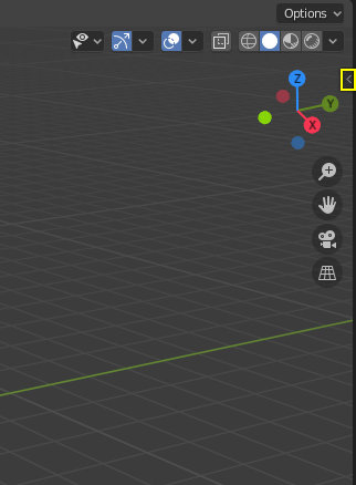 Image: Blender Manual (CC BY-SA 4.0)
The three default tabs
The Item tab shows the transform of the active object: its Location, Rotation, Scale and Dimensions. The Tool tab shows the settings for whichever tool is currently active in the Toolbar, so its contents change as the active tool changes. The View tab controls viewport settings such as the camera lens and the clip start and end distances, which determine when distant objects stop being displayed. This session works primarily in the Item tab.
The Item tab is the object's properties
The Item tab's Transform panel is where you read and set the object. It contains four fields, each with an X, Y and Z component. Location X Y Z gives the object's position in the scene. Rotation X Y Z gives its orientation in degrees. Scale X Y Z is a size multiplier whose default value is 1.0. Dimensions X Y Z is the real size in metres. As a reference point, the default cube has a Location of 0, 0, 0, a Scale of 1, 1, 1, and Dimensions of 2, 2, 2 metres, because the default cube measures 2 metres across. The distinction between Scale and Dimensions is the concept students most often confuse, so it is worth treating carefully.
Figure: the Item tab's Transform panel and its four fields.
graph TD
  IT[Item tab] --> TR[Transform panel]
  TR --> L[Location XYZ]
  TR --> R[Rotation XYZ]
  TR --> S[Scale XYZ]
  TR --> D[Dimensions XYZ]
Scale versus Dimensions
Both Scale and Dimensions describe size, but they mean different things. Scale is a unitless multiplier, while Dimensions is the measured size in metres. The two are linked representations of the same size, so changing one updates the other. A Scale of 2 applied to a 2 metre cube produces Dimensions of 4 metres. If you type 2 into Scale X, Dimensions X changes from 2 to 4; conversely, if you type 2 into Dimensions Y, Scale Y changes to 1. A caution follows from this: non-uniform scale can distort later steps, and animation or simulation setups often require Scale to be reset to 1. This is done with Object, then Apply, then Scale, a topic addressed fully in a later unit.
Figure: how a scale multiplier produces a measured dimension.
graph LR
  SC["Scale = 2.0"] --> CALC["x base size 2 m"]
  CALC --> DIM["Dimensions = 4 m"]
Editing a field: click, type, Tab
There are two ways to change a field. You can click and drag on it to slide its value, or single click to type into it. After typing a number, press Tab to jump to the next axis, which makes it efficient to enter X, Y and Z in sequence. Press Enter to confirm the edit or Esc to cancel it. Fields also evaluate simple arithmetic: typing 2*3 or 90/2 causes Blender to compute the result, giving 6 or 45 respectively. As a short exercise, set Location to 3, -1, 0 using only the keyboard and Tab.
The Toolbar
The Toolbar is a strip of tool icons on the left edge of the 3D Viewport, toggled with T. Clicking an icon makes it the active tool, and Shift Spacebar pops the Toolbar up at the cursor. The top tools are Select, Cursor, Move, Rotate, Scale and Transform. Hovering over an icon shows its name and shortcut, and dragging the Toolbar's inner edge widens it to reveal text labels beside the icons, which helps beginners. The key idea is the active tool: unlike a one-off shortcut, the active tool stays selected until another tool is chosen, and while Move is active a gizmo remains on the object at all times.
Figure: the top tools available in the Toolbar.
graph TD
  TB[Toolbar] --> SEL[Select]
  TB --> CUR[Cursor]
  TB --> MV[Move]
  TB --> RO[Rotate]
  TB --> SCA[Scale]
  TB --> TRN[Transform]
Active tool versus a quick shortcut
The active tool from the Toolbar remains active and always shows a gizmo, which suits initial learning. The G, R, S shortcuts each perform a single operation and need no gizmo, which is common in professional workflows. Neither approach is more correct, and both produce the same result. Many experienced artists keep the Select tool active and transform with G, R, S so their hands stay on the keyboard. The recommendation is to start with the Toolbar and then move on to G, R, S.
The transform gizmos
When Move, Rotate or Scale is the active tool, a gizmo appears on the object. Move shows arrows along X, Y and Z. Rotate shows coloured rings. Scale shows handles ending in small boxes. Transform combines all three. The axis colour code is consistent throughout Blender: X is red, Y is green and Z is blue. Dragging a coloured arrow moves the object along that single axis, while the small squares between the arrows move it along two axes at once within a plane. The white outer circle on the Rotate gizmo performs free rotation facing the screen.
Figure: the consistent axis colour code used by the gizmos.
graph TD
  G[Gizmo axes] --> X["X axis = red"]
  G --> Y["Y axis = green"]
  G --> Z["Z axis = blue"]
Interactive transforms: G, R, S
The interactive method follows one pattern: press a key, move the mouse, then click to confirm. G is Grab, meaning move, and comes from an earlier Blender term. R is Rotate and S is Scale. A left click or Enter confirms the transform; a right click or Esc cancels it and returns the object to its original position. No change is committed until you confirm, so pressing G, moving the mouse, then pressing Esc leaves the object unchanged. These three keys are among the most frequently used shortcuts in Blender.
Figure: the confirm or cancel flow of an interactive transform.
graph LR
  K["Press G / R / S"] --> M[Move mouse]
  M --> C{Confirm?}
  C -->|LMB / Enter| DONE[Applied]
  C -->|RMB / Esc| CANCEL[Cancelled]
Axis constraints and numeric entry
This is where G, R, S become precise. After starting a transform, tap X, Y or Z to lock it to that global axis. Tapping the same axis key twice switches to the object's local axis, which is visible once the object has been rotated. Use Shift X to move in the Y Z plane, that is, along everything except X; likewise Shift Z locks movement to the ground plane, useful for sliding objects across a floor. While transforming, type a number for an exact amount and press Enter. For example, G then X then 3 then Enter moves the object exactly 3 metres along the global X axis, and G, X, X switches to the local red axis.
Hands-on: place a cube two ways
The main practical outcome is to place a cube at the same location by two methods. Add a cube with Shift A, then Mesh, then Cube, and open the Sidebar with N. In the Item tab, set Location to 3, 0, 0 by typing and pressing Tab between axes. Undo with Ctrl Z, then press G, then X, type 3, and press Enter. Confirm that the Item tab reads Location X 3 in both cases. This shows that the Sidebar and G, R, S are two representations of one system: the numeric fields give precision and G X 3 gives speed. A common error is not clicking into the viewport first, in which case G has no effect.
Quick reference
| Category | Shortcuts |
|---|---|
| Panels | N Sidebar, T Toolbar, Shift Spacebar tool popup |
| Transforms | G move, R rotate, S scale, X Y Z axis |
| Confirm / cancel | Enter or left click confirms, Esc or right click cancels |
| Axis colours | X red, Y green, Z blue |
Summary
- The Sidebar (
N) is on the right edge of the Viewport and reports the active object's numbers through its Item, Tool and View tabs; the Item tab's Transform panel holds Location, Rotation, Scale and Dimensions. - Scale is a unitless multiplier and Dimensions is the measured size in metres; the two are linked, and non-uniform scale is later reset with Object, Apply, Scale.
- Fields accept click and drag, direct typing,
Tabto move between axes, and simple arithmetic such as2*3. - The Toolbar (
T) provides persistent active tools with gizmos, whileG,R,Sperform single transforms with no gizmo; both give the same result. - The axis colour code is consistent: X red, Y green, Z blue; constrain a transform with
X,YorZ, double tap for the local axis, andShiftplus an axis to exclude it. - The Sidebar reads the numbers and
G,R,Swith an axis and a typed number writes them precisely, as shown by placing a cube at Location X3two ways.